Electrotherapeutic Apparatus by Thomas H. Moray
This invention relates to electrotherapeutic apparatus, and to methods of applying electrical, radioactive, and other radiant phenomena therapeutically.
The invention is primarily concerned with the use of high potential, high frequency electricity though not necessarily limited thereto, in conjunction with radioactive and other types of electronic and radiation phenomena, for therapeutic purposes.
Among the objects of the invention are the following:
(1) To render highly effective, from a therapeutic standpoint, radioactive and other types of electronic and radiation phenomena, and likewise, to render highly effective, from a therapeutic standpoint, high potential, high frequency electricity.
(2) To augment the therapeutic effect of radioactive and other types of electronic and radiation phenomena by the conjoint use of high potential, high frequency electricity, and conversely, to augment the therapeutic effect of high frequency, high potential electricity by the conjoint use of radioactive and other types of electronic and radiation phenomena.
(3) To accomplish the above without danger of burning or otherwise harming the patient.
(4) To provide apparatus for accomplishing the above, which is relatively simple in construction and operation and relatively inexpensive to produce and operate.
(5) To provide novel electronic and radioactive devices especially adapted for use in conjunction with high potential, high frequency electrical therapy.
I have found that, be enveloping a patient in a high potential, high frequency field in such a manner that no closed circuit is completed through his body, radioactive and other electronic and radiation phenomena can be used therapeutically with considerably greater effectiveness than if used alone. The exact reason for this is not known, nor is it known definitely which, the electric field or the radioactive phenomena, acts upon the other to produce the advantageous results. It is thought, however, that the electric field permeating the body of the patient as it does attracts the radioactive emanations or radiations and enables them to penetrate considerably deeper into the tissues and vital organs of the patient than would otherwise be the case. In any event, remarkable therapeutic results have been achieved by use of the invention in the treatment of malignant tumors. Arthritis, sinus infections, and various other diseased conditions.
The invention contemplates the use, in therapeutics, of high potential, high frequency electricity to produce diversified forms of radiant energy, such forms being those which have been found best suited, individually, to benefit various human ailments. In accomplishing this purpose, several special discharge tubes have been developed to serve as treatment electrodes, by means of which correspondingly different curative results are obtained. Throughout the practice of the invention a prime consideration is that only one terminal of any particular circuit shall be contact with the patient's body at one time, so there will be no flow of current through a closed circuit of which the patient's body is a part. Such a terminal, too, is usually non-heat producing, so there is no danger of burning. In cases where there is a tendency for a tube to produce x-rays or other injurious rays, these are filtered out.
In the accompanying drawings, which illustrate several embodiments of apparatus preferred for carrying the method of the invention into practice:
Figure 1 represents a wiring diagram of a preferred embodiment of apparatus for carrying out the method of the invention in general therapeutic work, several independent treatment stations being provided;
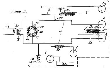
Figure 2 , a top plan view of the novel corona regulator of Figure 1, employed in the circuit to control and adjust the current and as a governor to safeguard the transformer;

Figure 3, a vertical section taken on the line 3-3 of Figure 2;

Figure 4, a vertical section taken centrally through one novel type of discharge tube used as a treatment electrode in the apparatus of Figure 1;

Figure 5, a horizontal section taken on the line 5-5 of Figure 4;

Figure 6, a vertical section taken centrally through another novel type of discharge tube used as a treatment electrode in the apparatus of Figure 1;

Figure 7, a horizontal section taken on the line 7-7 of Figure 6;
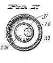
Figure 8, a vertical section taken centrally through a novel discharge tube used as a treating device in the apparatus of Figure 1;

Figure 9, a horizontal section taken on the line 9-9 of Figure 8;

Figure 10, a fragmentary vertical section taken on the line 10-10 of Figure 9;

Figure 11. a fragmentary view in vertical section, and drawn to a reduced scale, of a tub bath capable of use as a treatment station in the apparatus of Figure 1;

Figure 12, a view similar to that of Figure 11, but showing a shower or vapor bath arrangement for the same purpose;
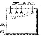
Figure 13, a wiring diagram similar to that illustrated in Figure 1, but fragmentary in nature, and of a somewhat different embodiment of apparatus;

Figure 14, an elevation, partly in central vertical section, of a novel tube use din the apparatus of Figure 13 in place of the corona regulator of Figures 2 and 3;
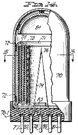
Figure 15, a top plan view, partly in horizontal section on the line 15-15 of Figure 14, of the tube of Figure 14;

Figure 16, a vertical section of another novel tube which may be used in place of the tube of Figures 14 and 15;

Figure 17, a vertical section taken on the line 17-17 of Figure 16;

Figure 18, a top plan view of still another novel tube which may be used in place of the tubes of Figures 14, 15, 16 and 17; and

Figure 19, a vertical section taken on the line 19-19 of Figure 18.

In accordance with the invention, provision is made for enveloping the patient in a high potential and, in certain instances, a high frequency electric field, and for applying to the patient, while so enveloped in the electric field, radiations and emanations having therapeutic value.
The apparatus of Figure 1 is capable of administering specific kinds of treatment, pursuant to the invention, at the several treatment stations provided. The treatment stations are indicated A, B, C, D, and E, respectively.
For supplying the high potential electric field, a suitable transformer is employed. This may be of any type capable of delivering high potential electricity, say from 10,000 to 30,000 volts. It is preferred, however, to utilize a conventional double magnetic circuit type of transformer, indicated at 10 in Figure 1, having adjustable laminated magnetic shunts (not shown), the transformer being connected across an ordinary power line 11 charged with the customary 115 volts. The output lines 12 from this transformer advantageously extend to the treatment stations A and B, respectively. The first secondary of the transformer 10 is preferably direct connected to the second secondary thereof. It is noted that this high potential electricity may be applied, without causing injury, direct to a patient who is not grounded. However, in order to safeguard the transformer 10 from damage by sparking across its output terminals, and to render the high potential electricity more suitable for therapeutic purposes, which is believed to include the automatic changing of frequency to an extent which depends upon the electrical characteristics of the patient's body, a governor or control device 14 is shunted across the leads 12.
This governor or control device 14 is a sparking condenser of high capacity embodying a multitude of spark gaps. A preferred embodiment of this governor or control device 14 is illustrated in detail in Figures 2 and 3.
As illustrated, the device comprises a cylindrical, electrically conductive plate 16 surrounded by a cylindrical dielectric 16. An outer cylindrical and electrically conductive elements 17 surrounds the dielectric 16 exteriorly. It is provided with a multitude (for example, 250) of inwardly extending prongs 17a, which are advantageously formed by stamping out and inturning triangular portions of the electrically conductive element 17. The internal plate 15 preferably contacts the interior surface of the dielectric 16, but in any event should lie closely adjacent thereto. Likewise, the tips of the prongs 17a preferably contact the outer surface of the dielectric. The several elements are advantageously mounted in a plug-in base 14a, which is adapted to mate with a suitable receiving socket (not shown) carrying the required electrical connections. He internal plate 15 connects with one of the electric lines 12, while the external element 17 connects with the other electric line 12, as shown diagrammatically in Figure 1.
It is preferable that the dielectric 16 be in the form of a closed tube or envelope, as shown, and be exhausted to vacuum condition. The multitude of sparking prongs 17a produce a brush discharge.
Where the dielectric 16 is not a closed tube or envelope, it is preferred that it be of quartz.
The treatment station A is a discharge tube of a novel type, exemplified by the tubes illustrated in detail in Figures 4, 5, 6, and 7. Either tube is plugged into the circuit of Figure 1 at a suitably provided single-terminal outlet. High potential electricity is, therefore, fed directly into the tube, which serves as an electrode. The tube also embodies radioactive material, which supplies radioactive emanations to the patient simultaneously with the electrical discharge.
As illustrated in Figures 4 and 5 the tube or electrode ay comprise an electrically conductive discharge element 20, having a support stem 20a and a major discharge cap or head 20b, which is preferably in the form of a thin, convex-concave plate. The head 20b may be spot welded to the end of the stem 20a.
The discharge element 20 is enclosed within a tube 21 of dielectric material, preferably glass, the stem 20a being fixed in the fused tongue portion 21a of the tube. The tube or shell 21 is fitted into an insulating base 22, provided with a single plug-in terminal 23, and an electrical connector 24 extends from the terminal 23 to the stem 20a.
The inside surfaces of the side walls of the tube or shell 21 are coated with a radioactive material, as at 25. The coating is conveniently made from uranium salts or powdered carnotite or other radioactive ore. The ends of the tube or shell are left uncoated.
Air is evacuated from the tube 21, and a small quantity of mercury introduced. The mercury is preferably triple-distilled to insure great purity. It is preferred that argon or like inert gas be also introduced.
Since the tube just described is plugged into the circuit of Figure 1, the discharge element or cathode 20 is charged with high potential electricity, and in its capacity of a treatment station in the apparatus of Figure 1, serves as an electrode to similarly charge the patient. The patient is insulated from the ground, and the tube is applied directly to the afflicted part of his body, preferably in close contact with the body.
Because of the construction of the tube, radiation of a radioactive nature is also directed against the patient through the uncoated top end of the tube. This radiation has been found to differ somewhat from the radioactive emanations discharging from the side walls of the tube, and is thought to comprise rays lying close to x-rays on the radiation spectrum. These rays appear to have a definite healing value, and lack the injurious nature of x-rays. Where a predominantly radioactive emanation treatment is desired, the side walls of the tube are placed against the body of the patient.
Best results are obtained when the discharge elements or cathode 20 is made of an alloy metal compounded from copper, lead, sulfur, and if desired, aluminum. The relative percentages of the several ingredients may vary considerably, but a satisfactory mixture comprises 5% copper, 55% lead, 30% sulfur, and 10% aluminum. Should aluminum not be used, the difference may be made up by additional copper.
In preparing the alloy, the copper and aluminum are heated to a molten state, after which the sulfur is added while stirring the mixture. After cooling, the mass is again melted, and the lead, in a molten state, is mixed with it, the molten mass being thoroughly stirred. This new mass is then cooled, being later reheated, and while hot, roiled to make it ductile so it can be shaped into the desired forms.
The discharge tube or electrode of Figures 6 and 7 is similar to that of Figures 4 and 5, having an enclosing tube or shell 26 which is evacuated. A cathode discharge element 27 is positioned within the shell, being fixed in the tongue portion 26a. A conductor 28 connects the stem 27a of the element 27 with a plug-in terminal 29, which extends outwardly of the base 30. The cap or head 27b of the element 27 differs from the cap or head of the electrode of Figures 4 and 5, in that it is spherical in form and hollow. It has an opening 31 formed at its top, contiguous with the top inside surface of the tube 26. A quantity 32 of radioactive material, which may be the same as used for the coating 25 of the electrode of Figures 4 and 5, is introduced into the tube or shell 26, along with a relatively small quantity of mercury, before the tube is sealed tight. Such material is preferably powdered or granulated, and is shaken into the hollow of the head 27b through the opening 31 before any given treatment is commenced. The mercury is provided primarily as a getter, and does no harm if shaken into the head 27b along with the radioactive substance. The mercury also tends to produce a vapor in the tube, which aids in the operation thereof. As in the case of the electrode tube of Figures 4 and 5, this tube may have a radioactive coating 33 covering the inner surfaces of its side walls.
The treatment station B of Figure 1 differs from the treatment station A only in the fact that a condenser 34 is interposed in the electric supply line 12.
The treatment station C of Figure 1 differs from the stations A and B only in the fact that the high potential electricity is supplied from the supply line 12 through an inductance 35.
The treatment station D utilizes a germicidal discharge tube, a preferred form of which is illustrated in detail in Figures 8, 9, and 10. The high potential electricity is taken by induction from the particular supply line 12 concerned. For this purpose, an induction coil 36 is provided, tapping the line 12 at 37. A pair of leads 38 from an ordinary 115 volt supply source extend to a plug-in socket connection for the germicidal tube, one of the leads passing through a glass tube 36a in Figure 1, which is disposed within and extends along the length of the induction coil 36. Thus, high potential electricity is impressed, by induction, upon the ordinary current flowing through the particular lead 38 concerned.
The germicidal discharge tube of Figures 8, 9, and 10 has a pair of discharge terminals 40 and 41, respectively, positioned in an evacuated tube or envelope 42, and electrically connected with plug-in terminals 40-l and 41-l, respectively, by means of stems 40a and 41a, respectively. The tube or envelope 42 and plug-in terminals are mounted in a conventional base 43. It is preferred that insulating material 44, such as a ceramic sleeve, covers the major portions of the stems 40a and 41a. A piece of lithium metal 45, see particularly Figure 10, is advantageously secured to the stem 40a adjacent the discharge terminal 40 to act as a getter. It may, however, be placed at any other convenient location in the tube. It is preferred that the discharge terminals 40 and 41 be formed of the special alloy previously described. Argon or other suitable inert gas is preferably injected into the tube or envelope 42, as is also a small quantity of mercury. The mercury, by vaporizing, aids electrical arcing between the discharge terminals. As will be noted, the high potential electricity induced in the one lead 38 will manifest at the upper discharge terminal 40, and will charge the patient simultaneously with the discharge into his body of germicidal rays from the tube.
The treatment station E embodies the tube of Figures 8, 9, and 10, as described above, but impresses the high potential electricity directly on the patient instead of passing it first through the tube. For this purpose, a discharge device 50, in the form of a soft, flexible pad in which a coil 50-1 is embedded, taps one of the high potential electric lines 12. This pad 50 is wrapped around the patient's body adjacent the afflicted portion thereof, thus charging the patient. Any other high potential electricity may be used in place of the pad 50. The germicidal tube has its terminals 40-1 and 41-1 plugged into a suitable plug-in socket connected to leads 52 which extend to an ordinary 115 volt source of supply. The high potential electricity with which the patient is charged is induced into the germicidal tube, thereby further activating the discharge therefrom. A certain beneficial discharge from this type of germicidal tube will be had by induced activation alone, it being unnecessary, in such instances, to plug the tube into the 115 volt line.
Other types of germicidal and discharge tubes may be sued in place of the tube of Figures 8, 9, and 10, as for instance the well known infrared and ultraviolet lamps, to produce results surpassing those ordinarily attained by the use of such lamps apart from the apparatus of the invention.
It should be remembered that the patient is insulated from the ground while being treated at any of the treatment stations of the invention.
Figures 1 and 12 show how a patient is treated pursuant to the invention, while immersed in an electrically conductive fluid bath. In Figure 11, a bath tub 53 is insulated from the ground by a layer of insulation 54. A treatment electrode of the type shown in any of the figure groups 4, 5, 6, 7, 8, 9, and 10 is positioned to charge the fluid of the bath with high potential electricity, as well as to discharge healing radiations and emanations into the patient. The particular electrode illustrated is diagrammatic in form and is designated 55. It may be connected into the circuit of Figure 1 as shown at any of the treatment stations A, B, C, and D. In Figure 12, a shower or vapor stall 56 is insulated from the ground by a layer of insulation 57. A plurality of treatment electrodes are designated 58. These correspond to the treatment electrode 55 of Figure 11. A water spray or vapor, such as steam, may be admitted to the stall 56 in any well known manner (not shown), thus enveloping the patient during treatment.
Another embodiment of apparatus, pursuant to the invention, is illustrated diagrammatically by the wiring diagram of Figure 13. While no treatment stations are shown, those provided are identical with the several treatment stations designated A, B, C, D, and E I Figure 1. The distinction in this embodiment of apparatus resides in the fact that a special generator of high frequency electricity is provided in the system.
A transformer 60 has its input terminals connected across an ordinary 115 volt electric line 61. Electrical conductors 62 and 63 lead from the respective output terminals of the transformer to a high frequency generator of the Oudin coil type, indicated generally at 64, a variable condenser 65 being interposed in the line 62, and the circuit being grounded at 66. Output conductors 67 and 68, leading from the high frequency generator 64, provide connection for the several treatment stations in the same manner as illustrated in Figure 1.
The transformer 60 may be any ordinary high voltage type. A governor or control device 69 is shunted across the conductors 62 and 63.
In the illustrated instance, the governor or control device 69 preferably takes the form of a vacuum tube, having the constructi9on shown by Figures 14, 15, 16, 17, 18 or 19. These tubes all possess high capacity and include elements effecting a brush discharge. They serve as does the device 14 of Figures 2 and 3.
The tube of Figures 14 and 15 embodies an outer shell or envelope 70 of insulating material such as glass, a plastic, or fiber coated with shellac. Inside the shell 70 is a bi-cylindrical element 71 formed of electrically conductive material. Separating element 71 from the enclosing shell 70 are spacers 72 made of rubber, bakelite, or other insulating material. Inter-fitting with the element 71 is a second electrically conductive, bi-cylindrical element 73, the two elements being separated by a dielectric 74. Inwardly of the element 73, and separated therefrom by a dielectric 75, is a corrugated, cylindrical element 76. The shell or envelope 70 is secured in an insulating base 70-1, provided with plug-in terminals. One of the terminals, designated 77, is electrically connected with the element 71, while another, designated 78, is electrically connected with the corrugated element 76. These two terminals connect with the conductors 62 and 63, as illustrated in Figure 13, and the brush discharge takes place at element 76.
Under certain circumstances, it is desirable that the outer shell 70 be made of quartz glass, and that a filament 79 be provided, the filament being heated by connection through plug-in terminals 80 and 81 with a source of low voltage heating current (not shown). Plug-in terminal 82, which is electrically connected with element 73, may be used instead of or in connection with the terminal 77, since element 73 acts in a manner similar to element 71. A getter 83 of suitable material, and an insulating an reflecting shield 84 may be provided, as shown. While the tube may have either a high or a low vacuum condition, or may be filled with an inert gas, I have also found it advantageous to fill the tube with a moist vapor. The tube acts as an oscillator for electric currents, and has an enormous capacity, a capacity many times that of a condenser of approximately equal size.
The tube of Figures 16 and 17 comprises an outer shell or envelope 85 which may be made of metal, glass, or fused quartz. This shell is mounted in an insulating base 86. Inside the shell 85 is a metal plate 87, and spaced apart therefrom, a corrugated metal plate 88. A plug-in terminal 89, which extends from the base, is electrically connected with the corrugated plate 88. These terminals are adapted to connect, through a suitable socket, with the electrical conductors 62 and 63 of Figure 13.
Under certain circumstances of use, it is desirable to have other elements in the tube. These are provided, and may be utilized or not as occasion warrants. A filament 91 is disposed between the plates 87 an 88. It is electrically connected with the two plug-in terminals 92 and 93, which are adapted to be connected to a source of low voltage heating current (not shown). A slit screen, comprising shields 94 and 95, with apertures 96 extending therethrough, is disposed adjacent that side of corrugated plate 88 which is remote from plate 87. The apertures 96 are in alignment with each other, and the shields 94 and 95 are made of lead or other material capable of screening off x-rays. Between shields 94 and 95 is a sheet 97 of material which is readily permeable to x-rays. Within the shell 85 there is also mounted a shell or envelope 98 of glass, quartz glass, or similar material, having a portion 98a which is ground like a lens and directed toward the slit screen. This shell 98 really constitutes a tube within a tube. A filament or cathode 99, comprising electrically conductive legs 99a and 99b and an electron-emitting portion 99c, is disposed within the shell 98, plug-in terminals 100 and 101 being electrically connected to the respective legs 99a and 99b. A bombardment element 102 is disposed within the shell 98 opposite the portion 99c of cathode 99. Within the shell 85, but outside the shell 98, is a reflector 103 directed toward the slit screen.
The tube of Figures 18 and 19 is essentially the same as the tube of Figures 16 and 17, being equipped with a shell or envelope 105, a base 106, a plate 107, and a corrugated plate 108, the two plates being connected to plug-in terminals 109 and 110 respectively, which are adapted to connect electrically with the conductors 62 and 63 of Figure 13. There is a filament 111 and an inner shell or envelope 112, but no slit screen. Instead of a lens portion being provided on the inner shell 112, a partition 113 of lens formation is disposed between the inner shell and the corrugated plate 108. It is fused to the walls of the outer shell 105. Within the inner shell 112 is a filament or cathode 114 which corresponds to the similar element 99 of the tube of Figures 16 and 17. A reflector 115 is directed toward the lens partition 113.
Reverting now to Figure 1, there is another advantageous way of treating a patient pursuant to the invention. As shown at Y, a foot pedestal 120 may be provided for making the patient a part of the condenser. The pedestal comprises an electrically conductive plate element or electrode 121, connected electrically with one of the high potential lines 12, and covered by an insulating platform 122 upon which the patient rests his feet while being treated at any of the previously described treatment stations A, B, C, D, or E. The electrode 121 and insulating platform 122 are conveniently mounted in a frame 123, which insulates the plate from the ground. The insulating platform 122 is made of a high quality insulating material such as first grade hard rubber. In certain instances it is desirable that the device be made in other than foot-pedestal form. For instance, it may be of cylindrical formation for use in a bed against any part of the patient's body.
If desired, the patient may be charged with the high potential electricity by direct contact with a metal or electrically conductive electrode in place of the pad 50 or treatment station E, or of the tube electrodes.
The invention has been described in the foregoing with sole reference to its use for therapeutic purposes. It should be noted, however, that inorganic matter may also be treated to advantage pursuant to the method and with the apparatus of the invention. It has been found that metals, for example lead, have changed physical properties after treatment in accordance with the above. In instances where the invention is not being used therapeutically, it is not always necessary to insulate the subject from the ground.
Whereas this invention is here illustrated and described with respect to particular specific embodiments thereof, it is to be understood that various changes may be made in such specific embodiments and various other embodiments may be utilized by those skilled in the art without departing from the spirit and generic scope of the invention as set forth herein and in the claims which here follow.
Related: Explanations of the Oscillations of Radiant Energy by Thomas. H. Moray
✰* Revealed At Last: Ancient Invention Generates Energy-On-Demand
The design includes:
- Harnessing electricity from the Earth: Neither is Schumann Resonance, nor is it known by Electromagnetism. It's Energy from Ether in Which the Earth Floats
- Extracted from ordinary electricity by the method called “fractionation.”
- Reverse Tesla coil - "Back to Back" mechanism
- Combination of radiant energy and negative resistance to amplify electricity
- And many other plans for Free Energy.


